

There are many use cases for 3D printing in our hobby. After a lot of testing and refinement my first successfully created part was a mounting option for a camera setup, I guess the most popular 3D printed FPV part. It was working much better than expected so that I started to think about other parts and finally ended-up in a new frame design for tiny brushless whoops.
This article was submitted through the GetFPV Community Program by Kolibri F.
Disclaimer: This article was written solely by a member of the FPV Community. Views and advice in this article are that of the author and does not necessarily reflect the opinion or views of GetFPV.
Figure 1 (cover): Assembled frame and example low profile setup with top mounted battery, bottom mounted fc and camera in front (latest design comes with camera mount that supports 14 mm boards like RunCam Nano 3).
In this article I want to share with you a printable whoop frame that combines the strengths of two interesting materials: polypropylene and bamboo toothpicks. The design looks crazy and before you stop reading, I can already tell that it seems to do very well and can easily be produced on an entry level 3D printer at low cost. All needed files are published at Thingiverse and printed parts can be assembled with basic skills and tools.
Why?
There are other examples shared on Thingiverse and with R3D Shifters there is even a company selling 3D printed frames. But I was quite doubtful about competing with low-priced, lightweight and robust injection molded plastic whoops frames. You simply could not do much better.
Anyhow, I decided to do a feasibility study for a prop guard with my preferred polypropylene filament, essentially expecting to prove my assumption to be too heavy, too weak or both. To my surprise, the first result was not completely out of range so that I started with a frame design, somehow still expecting to produce a lame duck. My motivation was not to do better, but simply to have a better way to mount my camera.
The specs of the frame
Frame size (from motor post to motor post): ~60mm for 31mm prop size
Weight: ~3.2 to 3.6g
whoop frame
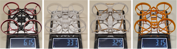
Figure 2: Weight comparison with other 65 mm frames, from left to right:
(1) stiff but heavy: Snapper 6 (carbon + aluminium) 6.15g, (2) de-facto standard plastic 65 mm frame from Happymodel (used by Mobula 6 and others) 3.31g, (3) printed 60 mm frame 3.29g and (4) 65 mm alternative from BETAFPV 3.15g.

Figure 3: Size comparison with 65 mm frame from BetaFPV.
Going smaller than 65 mm means a more compact design that requires less material, leading to some welcome weight savings. A 31 mm prop size allows it to go down to 55 mm or even less, but then you get problems with mounting your battery and flight controller. I stopped at around 60 mm, which overall seems to be a good compromise. It also helps to pass little smaller gaps, which in the end can give you a feeling of higher speed. But that is a little bit of theory and in fact a lot of people prefer the bigger 75 mm class due to better flight characteristics.
We will see if going smaller is actually a good idea. So far, my experiences are promising and I think there is a lot of potential, in particular seeing firmware developments.
Design principles and used materials
3D printing gives you a lot of interesting design options. One of them is to create hollow profiles, which is a great way to reduce weight. Another well-known principle of strong and at the same time lightweight support structures is a truss framework. Both principles are combined in the presented design.
The idea is to use hollow profiles for the prop guards and thin, but strong sticks to realize the motor mount. By accident I came across with toothpicks, which turned out to be a perfect choice for the sticks. I recommend using the stronger version made of bamboo instead of wood, but both should be fine. It is even better than carbon fibre because they are a bit lighter and easier to work with.
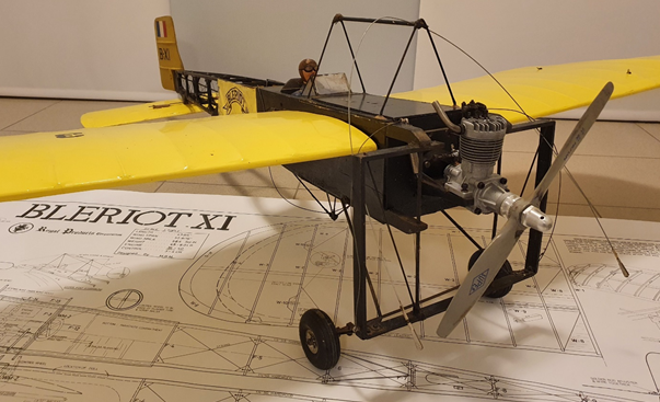
Figure 4: Wooden framework structures from early days – RC model from the 70’s of the Bleriot XI from 1909
An important question was already answered by my initial camera mount design, namely if both materials can be securely connected. The key factor for a strong and durable connection is to use a flexible material with high tensile strength.
When looking for a suitable filament I was first thinking of carbon-nylon, as preferred by other designs, but then discovered polypropylene, which has a rather low shore hardness of D50 and thus does not seem to be a good solution at first glance. I was mainly attracted by the low density of around 0.9 g/cm³ and then also discovered the good layer adhesion that together with a high elongation at break property (~600%) is leading to almost unbreakable parts. You do not even need glue to securely connect the sticks with the prop guards and motor mounts.
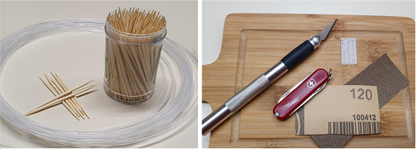
Figure 5: Standard toothpicks with 65mm length and 2mm diameter and transparent PP filament + tools needed for assembling the frame.
I am using Formfutura Centaur PP Filament for my prints, which I ordered as a sample of 50g. It is available in three colors: black, white, and natural/transparent. There is also an ultralight version with a density of only 0.75 g/cm³, Formfutura Pegasus PP, which however did not perform as expected and thus cannot be recommended by me.
Frame design with OpenSCAD – a parametric CSG modeler
The typical workflow for 3D printing is to start with a CAD tool of your choice to model the parts. It is then exported as an STL file to be translated by your slicer tool into print commands for your 3D printer. While the first step defines the external shape, internal properties can be controlled by printer settings like wall thickness, infill and others. It means that we do not have to model the hollow prop guards because it can be configured more easily in the second step. More about this in the next section.

Figure 6: Frame design with OpenSCAD: Script and rendered view.
Defining the external shape of your design also requires defining all cutouts as needed for screw holes or the openings for mounting the toothpicks. Such cutouts are best to handle with a modelling method called Constructive Solid Geometry (CSG), which enables to combine two solid bodies with Boolean operations such as union, difference and intersection. Consequently, we first model both, the solid connection part and the toothpicks. In a second step we subtract the toothpicks from the connection part in order to create the right cutouts. So, CSG is a quite simple modelling principle.
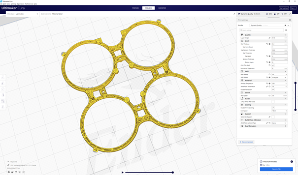
Figure 7: Printer settings in Ultimaker Cura – hollow design controlled by infill parameters.
Finding the right dimensions for a tight fit of the toothpicks, the size of prop guards (mainly to have enough clearance space) or even the whole frame size requires some iterations. A parametric design can speed-up this optimization process because it allows you to change the design by adjusting your design parameters, like for instance the toothpick diameter. Accordingly, the design must be encoded in a script, which then only needs to be recompiled after changing a particular parameter. This is quite convenient as soon as such a script is in place.
More details about parametric modelling and other design aspects might be a topic for another article. If you are interested in doing your own design then check out for instance OpenSCAD, which is free software and was also used for this design.
Printer Settings
There are only a few things that are important when printing with polypropylene. The first one is to use packing tape like Tesa to improve bed adhesion. The second one is to consider the shrinkage of the material, which can be handled by increasing the size of the parts to around 103%. The rest is mainly to play with print parameters to optimize the result, meaning to find the best compromise between weight, stiffness and print quality.
I am using the following settings in Ultimaker Cura for the Ender 3 printer with a standard 0.4 mm nozzle:
- Nozzle temperature: 235°C
- Bed temperature: 75°C
- Infill: 25% (infill pattern Triangles)
- Wall thickness 0.4 mm (play with other values and nozzles)
- Print speed: 30 mm/s
- No support and no skirt or brim
The frame is already designed to be printed without support structures. Make sure that you use the best orientation of your parts, i.e. to put everything on the ground without too much overhang. The files published at Thingiverse are ready to print, but still need to be scaled.

Figure 8: Printing the frame with the help of PP packing tape.
Parts and assembly
Before starting to assemble the printed frame parts you need to cut the toothpicks to the right size, and very important, to bevel both ends of the sticks as shown below. I am using toothpicks with 2 mm diameter and 65 mm length, which seems to be the standard size. There are two different lengths, 4 x 21.5 mm and 8 x 23.5 mm. Make sure that the lengths are equal and as exact as possible. Otherwise you will get an egg-shaped prop guard and a warped frame. This is the most critical part, and be aware that the sticks will have a tight fit. This needs a little bit of care and accuracy. The design includes a cutting gage that helps to cut the sticks at correct lengths.
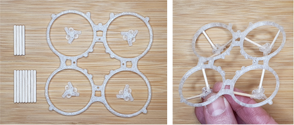
Figure 9: Parts (12 toothpick sticks, 4 motor mounts and frame) and assembled frame.
When putting everything together I recommend to begin with the assembly of the motor mounts and then, one by one, attach the sticks to the prop guards of the frame. Here you should start with the longer sticks that go to positions where the prop guards connect to each other. You should finish with the shorter stick that connects to the position pointing away from the flight controller. The connection to the motor mount is twisted, two parts are oriented clockwise and the other two are counter clockwise. Make sure that the right motor mount is attached to the right prop guard. If everything is assembled the frame should look as shown in the figure above.
All electronics are standard parts and can be swapped from an existing brushless whoop. The slightly smaller frame size of ~ 60 mm is leading to some constraints for the flight controller. At the time of writing this article the best fit is the F4 1s flight controller from the Eachine UZ65 whoop. It comes with rounded edges, the right distance of the USB port and good solder pads for the motors. This gives you more options for your build.
Parts list
- 0802 or 0603 brushless motors,
kV rating according to your power requirements - Standard 1s Flight Controller with 25.5 mm mounting holes
BETAFPV boards as used in the example or Eachine AIO Superbee F4
For the shown setup I decided to install a board from BETAFPV that was already waiting to be used. The flight controller is mounted with M2x8mm nylon screws below the prop guards. You can directly screw into the frame and thus do not need an extra nut. If the flight controller is mounted below the frame, the battery must consequently go to the top. It can be secured with two rubber bands and a little bit of additional protection from the props. I tested some sort of guide bars as shown in the figure below. The frame allows mounting of the battery in both orientations, in the nick and roll axis.

Figure 10: Tested flight controllers and finished whoop on a scale (with super lightweight Eachine TX06 camera).
The camera mount follows the latest trend of low-profile whoop designs as for instance made popular by Mr. Shutterbug. But instead of using glue I am again using a short toothpick and some rubber band to fix my low cost and lightweight camera. By this construction, the camera angle is very easily adjustable and should securely stay in place.
Conclusion and next steps
In this article we have seen a new frame design for tiny whoops, a true toothpick frame if you like ;-). The example build is a proof of concept and can be equipped with your preferred setup and can be modified to your likes. There are a couple of interesting options and tunes. You may want to go lighter and want to play with printer settings, or you can even modify the whole design. There are countless options! May give it a try and start to assemble your own whoop.
To finish off and to make you a little bit curious; I did not show my camera mount that was the motivation of the whole project. This little extension brings the frame on another level and makes it even more competing. If time allows and you are interested, this might be a topic for another article.
Mepsking FPV Forum, where you can learn everything about drone and flying skills. Check mepsking store if you want to buy drone parts.